Showing posts with label what. Show all posts
Showing posts with label what. Show all posts
Monday, March 27, 2017
What is Kali Linux
What is Kali Linux
Kali Linux is an advanced Penetration Testing and Security Auditing Linux Distribution, based on Debian development standards. Kali Linux- a complete re-built of Backtrack Linux, was developed by Offensive Security. Kali Linux is completely open source and come free of cost. It offers more than 300 penetration testing tools with timely security updates, support for the ARM architecture, a choice of four popular desktop environments and seamless upgrades to newer versions. Kali Linux is distributed in 32-bit and 64-bit images for use on hosts based on the x86 processor architecture, as well as an image for the ARM architecture for use on the Raspberry Pi computer, rk3306 mk/ss808, ODROID U2/X2 and on Samsungs ARM Chromebook.
Earlier release of Kali Linux:
Kali 1.0.2 – 27th March, 2013 – Minor Bugfix Release and update roll-up.
Kali 1.0.1 – 14th March, 2013 – Minor Bugfix Release.
Kali 1.0 – 13th March, 2013 – Initial release.
Available link for download
Friday, March 24, 2017
What is Slave Select SS in SPI
What is Slave Select SS in SPI
There’s one last line you should be aware of, called SS for Slave Select. This tells the slave that it should wake up and receive / send data and is also used when multiple slaves are present to select the one you’d like to talk to.
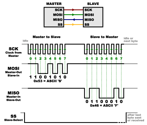
The SS line is normally held high, which disconnects the slave from the SPI bus. (This type of logic is known as “active low,” and you’ll often see used it for enable and reset lines.) Just before data is sent to the slave, the line is brought low, which activates the slave. When you’re done using the slave, the line is made high again. In a shift register, this corresponds to the “latch” input, which transfers the received data to the output lines.
Multiple slaves
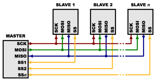
There are two ways of connecting multiple slaves to an SPI bus:
- In general, each slave will need a separate SS line. To talk to a particular slave, you’ll make that slave’s SS line low and keep the rest of them high (you don’t want two slaves activated at the same time, or they may both try to talk on the same MISO line resulting in garbled data). Lots of slaves will require lots of SS lines; if you’re running low on outputs, there are binary decoder chips that can multiply your SS outputs.
- On the other hand, some parts prefer to be daisy-chained together, with the MISO (output) of one going to the MOSI (input) of the next. In this case, a single SS line goes to all the slaves. Once all the data is sent, the SS line is raised, which causes all the chips to be activated simultaneously. This is often used for daisy-chained shift registers and addressable LED drivers.
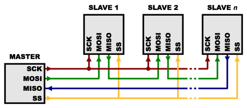
Note that, for this layout, data overflows from one slave to the next, so to send data to any one slave, you’ll need to transmit enough data to reach all of them. Also, keep in mind that the first piece of data you transmit will end up in thelast slave.
This type of layout is typically used in output-only situations, such as driving LEDs where you don’t need to receive any data back. In these cases you can leave the master’s MISO line disconnected. However, if data does need to be returned to the master, you can do this by closing the daisy-chain loop (blue wire in the above diagram). Note that if you do this, the return data from slave 1 will need to pass through all the slaves before getting back to the master, so be sure to send enough receive commands to get the data you need.
Source :https://learn.sparkfun.com/tutorials/serial-peripheral-interface-spi/slave-select-ss
Available link for download
Monday, March 20, 2017
What Is Buoyant Force
What Is Buoyant Force
What Is Buoyant Force?
Buoyant force is an upward force that fluids exerts on any object that is placed in them. The ability of fluids to exert this force is called buoyancy . What explains buoyant force? A fluid exerts pressure in all directions, but the pressure is greater at greater depth. Therefore, the fluid below an object, where the fluid is deeper, exerts greater pressure on the object than the fluid above it. You can see in theFigure below how this works. Buoyant force explains why the girl pictured above can float in water. ?

Q : You’ve probably noticed that some things don’t float in water. For example, if you drop a stone in water, it will sink to the bottom rather than floating. If buoyant force applies to all objects in fluids, why do some objects sink instead of float?
A : The answer has to do with their weight.
Weight and Buoyant Force
Weight is a measure of the force of gravity pulling down on an object, whereas buoyant force pushes up on an object. Which force is greater determines whether an object sinks or floats. Look at the Figure below . On the left, the object’s weight is less than the buoyant force acting on it, so the object floats. On the right, the object’s weight is greater than the buoyant force acting on it, so the object sinks.

Because of buoyant force, objects seem lighter in water. You may have noticed this when you went swimming and could easily pick up a friend or sibling under the water. Some of the person’s weight was countered by the buoyant force of the water.
Density and Buoyant Force
Density, or the amount of mass in a given volume, is also related to the ability of an object to float. That’s because density affects weight. A given volume of a denser substance is heavier than the same volume of a less dense substance. For example, ice is less dense than liquid water. This explains why the giant ice berg in the Figure below is floating in the ocean. You can see other examples of density and buoyant force at this URL:
http://www.youtube.com/watch?v=VDSYXmvjg6M

Q : Can you think of more examples of substances that float in a fluid because they are low in density?
A : Oil is less dense than water, so oil from a spill floats on ocean water. Helium is less dense than air, so balloons filled with helium float in air.
Summary
- Buoyant force is an upward force that fluids exert on any object that is placed in them. Buoyant force occurs because the fluid below an object exerts greater pressure on the object than the fluid above it.
- If an object’s weight is less than the buoyant force acting on it, then the object floats. If an object’s weight is greater than the buoyant force acting on it, then the object sinks.
- A given volume of a denser substance is heavier than the same volume of a less dense substance. Therefore, density of an object also affects whether it sinks or floats.
Available link for download
Wednesday, March 15, 2017
What is Quiescent Current
What is Quiescent Current
The term given to describe the amount of current consumed by a circuit when it is not performing any work (sometimes referred to as standby current). This is a particularly important concept in designing battery-operated systems such as wireless beltpack transmitters. Battery life is determined by the total current drain composed of quiescent current and load current. Usually battery-operated devices are in standby mode more than in operation mode so the quiescent current consumption is the more dominant consideration. Quiescent current consumption should be as low as possible in order to prolong the battery’s life.
Class A amplifiers have the general property that the output device(s) always carry a significant current level, and hence have a large quiescent current. The quiescent current is defined as the current level in the amplifier when it is producing an output of zero. Class A amplifiers vary the large quiescent current in order to generate a varying current in the load, hence they are always inefficient in power terms.
Source: http://www.sweetwater.com/insync/class/
Available link for download
Saturday, February 25, 2017
Basic Electricity What is an amp
Basic Electricity What is an amp
Basic Electricity - What is an amp.
Watt Is An Amp?
Frequently Asked Question:
What is a watt? What is an amp? And why is it important for me to know how many watts or amps my equipments draws? This is a very good and much asked question. Its important to know how much electricity your equipment consumes, because all sources of power are finite. Whether youre connected to a battery, a standard AC wall outlet, or the power pole outside your theater, theres a limit to the quantity of power available (albeit a pretty BIG limit, when it comes to the poles power line :-) This answers the last
part of the question, because knowing the wattage or amperage (along with the voltage) allows you to determine the type of power source required to operate your equipment. Now the first parts . . . An amp is a unit of electrical current. The quantity tells you how much electricity is being drawn through the power cable. A product that draws 10 amps sucks twice as much electricity as a product that draws 5 amps. (Thats why it needs thicker wires.) A watt is a unit of electrical power. The quantity tells you how quickly electricity is being consumed through the power cable. "Consumption" differs from "draw" in that its relative to voltage, while draw is not. Two products may both draw 5A (5 amps), but if one is 12V and the other 6V, the 12V product will consume twice as much electricity as the 6V product. The 12V product will consume twice as many watts as the 6V product, even though they both draw amps at the same rate.* P=IV Power = Current x Voltage Watts = Amps x Volts All of these equations say the same thing. You multiply amps by volts to determine watts. Or you divide volts into watts to determine amps. Most equipment will specify the voltage required, and either the current draw (amps) or power consumption (watts); once you know two of the figures, you can use the above equation to calculate the third. An example is in order. Most electrical products draw 120 VAC. Most electrical circuit breakers are rated at 20A. 20x120=2,400; therefore, you can plug 2,400W of equipment into most AC wall outlets and know that the breaker will not kick.** Well thats pretty much it for watts and amps. * Purists may flame me for using the term "consumption" in association with "Watts", but I believe I made it clear that I was talking about the "rate" of consumption, not the actual consumption itself. Power "consumption" is measured in Watt-Seconds, or Joules. (But unless you plan to dispute your electric bill with the utility company, its really not necessary for you to know this. :) ** An individual standard wall outlet is usually rated at 15A. There are usually a number of these outlets on one 20A breaker. You can draw a total of 2,400W by using two or more of these outlets. You cant actually plug 2,400W into one 15A outlet, as the article may have implied.
Available link for download
What To Do If Your Hotmail Account Gets Hacked
What To Do If Your Hotmail Account Gets Hacked

Steps To Be Taken By You Once You Find Out Your Hotmail Account Is Hacked :
Now that you have a strong idea that your Hotmail account has been hacked, you shall need to take immediate steps to retrieve the situation. We present a list of immediate actionable steps to be taken by you. However, before we go into the details, in case of any confusion in following the instructions given by us, we advise you to please use the Hotmail customer service contact number and get the help of the Microsoft service team to help deal with the problem.Step 1 : Free Your PC From Malware Or Virus
Download and install a reputed anti-virus and anti-malware system such as the Microsoft Security Essentials (for a Windows 7 operating system) and Microsoft Defender ( for a Windows 8 operating system). Make certain of running a full scan of your system. And only after that, change your Hotmail account password.Step 2 : Reset Your Hotmail Account Password
Once you have fully completed the scanning of your system, log in to your Hotmail account and reset your password. While selecting a new password, you shall need to make completely sure that you use something that is totally different from the old one. Please do not use any of the commonly used passwords that may be found in many accounts, such as "passwd" or "admin". Use something much more complicated. Make use of capital letters, symbols, lower case letters and numbers. But do make sure that this new password may be easily remembered by you. Run your password through Microsofts password checker to make sure it has never been used before by anyone. And once set, make sure of changing your password at regular intervals.Step 3 : Change Your Account Settings
Make sure of resetting your Hotmail account settings. Click on the "more mail settings" field in the "Options" tab and follow the instructions given on how to reset the various options available in your Hotmail account.Step 4 : Get Back The Deleted Mail
One of the most important signs that your Hotmail account has been hacked is the sheer number of deleted mail. Once the Microsoft mail server has an inkling that your account is being hacked, it saves all the deleted mail in a special "Deleted" folder. Click on this folder, and opt for for "restore deleted mail" option. Now you are good to go!Summary:
Hacking of the Hotmail account of private individuals is a serious problem that has become very common of late. The first step in dealing with it is to check for the signs that tell you whether your Hotmail account has been hacked or not. Then the instructions given in this article should be followed step by step to help in retrieving the situation.Image Credit: Stuart Miles
Author Bio:
Smith is a professional programmer from NewYork , who has often been the victim of a Hotmail hack, and has found using the Hotmail customer service contact number a mighty useful way to deal with this mini-crisis. Besides helping out people who are under attack from dangerous hackers, He dabbles in photography and hates global warming.Available link for download
Sunday, February 19, 2017
What is a constant power load Constant current load and Constant resistance load
What is a constant power load Constant current load and Constant resistance load
Constant resistance load:
In a constant resistance load the current will go down in proportion to the voltage drop as the resistance is fixed and the load must follow ohms law. Heaters approximate this type of load.
Constant current load:
In a constant current load the load will dynamically adjust its resistance as the voltage drops to keep the current constant. Thus as the battery voltage drops so will the equivalent resistance of the load. Older linear regulators using a pass transistor to deliver constant voltage to a fixed load powering electronics are this kind of load.
Constant power load:
In a constant power load, the dynamic resistance is adjusted to increase the current inversely to the load voltage. as the voltage rises or falls, then the product of voltage and current in the load is power which is constant. This is done to keep the power dissipated in the load constant as the voltage drops. Electronics devices with SMPS approximate this type of load as they generally employ regulators to generate a constant voltage and when then runs the electronics.
Real loads usually approximate one of the three types of load. Electrical engineers have as one of their tools electronics loads which can be programmed to emulate the load types above.
Source : Quora
Available link for download
Friday, February 17, 2017
What is Motherboard
What is Motherboard
 |
| What is Motherboard? |
1.What is Motherboard?
The motherboard serves to connect all of the parts of a computer together. The CPU, memory, hard drives, optical drives, video
card, sound card etc. connect to the motherboard directly or via cables.Available link for download
Sunday, January 29, 2017
What is 555 Timer How it Works
What is 555 Timer How it Works
555 Timer
Timers
Timers are those circuits, which provide periodic signals to a digital system which change the state of that system. In other words, those circuits, which work on the base of multivibrator changes or a device, which can be used as multivibrator is called Timer. (We will discuss Multivibrator in detail in next coming posts)
555 Timer
555 Timer is a digital monolithic integrated circuit which may be used as a clock generator. In other words, 555 Timer is a circuit which may be connected as a stable or monostable multivibrator.
555 Timer is a versatile and most usable device in the electronics circuits and designs which work for both stable and monostable states. It may provide time delay from microseconds up to many hours.
Below is the pin diagram of DIP (Dual inline Package) 555 timer with 8 pins.

555 timer is a very cheap IC which works for wide range of potential difference (typically, from 4.5 to 15V DC) and the different provided input voltages do not affect the timer output.
555 Timer is a linear device and it can be directly connected to the CMOS or TTL (Transistor – Transistor Logic) digital circuits due to its compatibility but, interfacing is must to use 555 timer with other digital circuits.
555 Timer Construction
There are lots of manufacturers who manufacture 555 timer which included the number 555 e.g. NE555, CA555, SE555, MC14 555 etc. typically, two 555 timers sandwiched inside a single chip which is called 556. Nowadays, chips are available with four 555 timers in it. These devices are available in circular IC with eight (8), DIP (Dual inline Package) with 8 pins or DIP with 14 pins.
Here is the simple explanation of the 8 pins of 555 Timer.
1. Ground (GND)
It’s the common ground point of the circuit. The ground terminal of external circuit as well as power supply (Vcc) ground terminal is connected with this i.e. GND (Ground) terminal of 555 timer.
2. Trigger
When Trigger terminal gets one –third (1/3) of the supply voltage i.e. Vcc/3 equal amplitude’s negative trigger pulse, then the circuit output changes form Low to High.
3. Output
This terminal is used for getting output and connected with load. At any instant, its value is low or high.
4. Reset
Without taking into account the previous state of output, by providing a trigger pulse to this terminal resets the device. I.e. Its output becomes low.
5. Control Voltage
There are two third positive voltages of the total Supply voltages (Vcc) at control voltage terminal. Thus, it becomes a part of the comparator circuit. Generally, a capacitor is connected between ground and voltage control terminals.
6. Threshold Voltage
Threshold voltage and control voltage is the two inputs of comparator circuit. The circuit compares the available voltage at threshold voltage terminal to the available reference voltage at control terminal.
If the available voltage at threshold terminal (Pin 6) is greater than the control voltage i.e. two-third of Vcc, then the output would be low, otherwise, it would be high.
7. Discharge
When output is low, then Discharge terminal provides a low resistance discharge path to the externally connected capacitor. However, it acts an open circuit, when output is high.
8. +Vcc (Supply Voltage Terminal)
Supply voltage is provided at this terminal for timer operation.
A simple 555 timer circuit is shown below in fig _ which shows the internal construction of 555 timer. According to the fig, the timer contains on two comparators, an RS flip flop, an Output stitch (output buffer) and a Discharge Transistor Q1.
In addition, there are three 5k? resistors are connected in series with 5k? resistor which first end is connected with Vcc (Pin 8 = Supply voltage) and the other end is connected with ground (GND = Pin 1).
Good to Know: due to the three 5k? series connected resistors, this IC timer chip is called 555 Timer J.
Working Principle of 555 Timer

In the 555 Timer block or functional diagram, comparators are those devices which output is high, when their positive input voltage is greater than their negative input voltage and vise versa.
The voltage divider in the circuit (which contains on three series connected 5k? resistors), which provides the trigger level of one-third of Vcc (Vcc/3) and two-third (2/3) of threshold voltage. To understand this point, suppose the input value is 15V. In this case, the value of trigger level would be 5V as (Vcc/3 = 15V/3 = 5V). And the value of threshold level would be 10V as (Vcc x 2/3 = 15V x (2/3)) = 10V.
When needed, the trigger level and threshold can be adjusted by using the Control Voltage terminal (Pin 5) i.e. by changing the control voltage at Pin 5, we may change the trigger level and threshold voltage according to the required specification. However, in this case, the value of trigger and threshold would be remain equal to 1/3 Vcc and 2/3 Vcc respectively.
When the normal high trigger input value instantaneously reduce then the 1/3 Vcc, Then the output of Comparator B becomes High from Low, as a result, RS latch or RS Flip flop goes to “set”. When flip flop goes to set, then Output (at Point 3) becomes high. Simultaneously, the discharge transistor Q1 gets off and The output remains high until the value of normally low threshold input does not increase then the 2/3 Vcc.
As soon as the threshold input increase than the 2/3Vcc, then the output of comparator A becomes Low, as a result, RS flip flop get reset (because the output of comparator is directly connected to the RS flip flop’s input R as shown in the fig). When flip flop gets reset, output becomes low and discharge transistor Q1 goes to on.
The flip flop can be reset by applying external input reset without threshold circuit. Note that, the trigger and threshold inputs (Pin 2 and Pin 6) are controlled by externally components and the 555 timer can be used for Available link for download
Read more »
Tuesday, January 24, 2017
What Is the Purpose of a DDoS Attack
What Is the Purpose of a DDoS Attack
Distributed Denial of Service (DDoS) attacks are usually done by individuals calling themselves “hacktivists.” Their purpose is to crash a website server by overwhelming it with activity by “bots” and is generally an aim with a political purpose. These attacks can take up 111gbps to 179gbps, and in April of 2013, took 144 million packets-per-second. If the “hacktivists” are against a company’s stance on a specific issue or multiple issues, the “hacktivist” will attack in an attempt to show opposition and illustrate the company’s weakness. A “hacktivist” may also attack a company, such as a bank or finance company, which they believe makes money off of the downtrodden of society. Some hackers have used DDoS attacks for extortion in an attempt to make companies pay a designated amount before their servers can go back online. A DDoS attack can even be carried out by hackers who deem the company in competition with another company the hacker supports. It is also beginning to look like DDoS attacks are being used in fraud techniques and many alerts have been issued to companies to be aware of these possible attacks.

Created by the marketing team at Prolexic Technologies.
Available link for download
Monday, January 23, 2017
What a Powerful Windows 7 Password Recovery!
What a Powerful Windows 7 Password Recovery!
A powerful windows 7 login password provides a layer of protection for your private data, but it may be difficult that you should keep an eye on it. How to proceed should you forgot windows 7 password?
Should you register with Microsoft account, go to Microsoft account sign-in web page and totally reset it. Should you register having a local user account, following information is going to do a favor.
Windows 7 enables you to produce a password hint and password totally reset disk in front of failing to remember the password. Then when you forgot windows 7 password, you will get back or login windows PC using the following techniques:
* Recover windows 7 password with the password hint.
* Totally recover windows 7 password having a formerly-produced password totally reset disk.
* Totally reset windows XP password using another admin account.

Recommendation: Windows Password Recovery
The windows 7 password recovery techniques in the above list are helpful, but may be not appropriate for both you and your situation. For the reason that situation, the very best option would be to produce a boot password totally reset disk to break Windows 7 password. To get this done, you just need a competent windows password totally reset utility.
Windows Password Recovery is a well-liked windows password totally reset tool liked by most lost windows password customers. It enables you to definitely bypass any forgotten Home windows password by burning a boot password totally reset disk with Compact disc/DVD or USB memory stick. It supports windows 8/7/Vista/XP/2008/2003/2000. Following may be the how-to:
Part1: Produce a boot windows 7 password totally reset disk
Step One: Install the windows password totally reset tool in almost any windows-based computer that you could run as administrator.
Next, place a USB memory stick or Compact disc/DVD in computer and launch the installed application, after which click Burn USB or Burn Compact disc/DVD button to create Windows 7 password reset disk. The password totally reset disk is going to be burned inside a couple of seconds.
Part 2: Totally reset Forgotten windows 7 password with boot disk
Step One: Place the burned boot password totally reset disk within the computer you need to totally reset password of.
Step Two: Energy on the pc and hang it boot in the placed disk. After loading files, Windows Password Recovery with your windows 7 user aaccounts can look.
Step Three:Choose the consumer account you need to totally reset password of and click on Totally reset button.
Step Four:Click OK whenever a dialog box appears to see if you’re sure to totally reset the password from the selected windows 7 user account. And also the windows 7 user password is going to be totally reset immediately.
Step Five : Click Reboot button to restart the pc. Please take away the placed boot disk throughout restarting.
Once the windows 7 logon screen seems, sign in it without password. That’s all! The entire windows 7 password recovery process can cost you a maximum of a few minutes. 100% secure. No data loss or damage. You don’t need to feel frustrated whenever you forgot windows 7 password.
For more: http://www.powerpointpasswordrecovery.net/windows-7-password-recovery.html
Should you register with Microsoft account, go to Microsoft account sign-in web page and totally reset it. Should you register having a local user account, following information is going to do a favor.
Windows 7 enables you to produce a password hint and password totally reset disk in front of failing to remember the password. Then when you forgot windows 7 password, you will get back or login windows PC using the following techniques:
* Recover windows 7 password with the password hint.
* Totally recover windows 7 password having a formerly-produced password totally reset disk.
* Totally reset windows XP password using another admin account.
Recommendation: Windows Password Recovery
The windows 7 password recovery techniques in the above list are helpful, but may be not appropriate for both you and your situation. For the reason that situation, the very best option would be to produce a boot password totally reset disk to break Windows 7 password. To get this done, you just need a competent windows password totally reset utility.
Windows Password Recovery is a well-liked windows password totally reset tool liked by most lost windows password customers. It enables you to definitely bypass any forgotten Home windows password by burning a boot password totally reset disk with Compact disc/DVD or USB memory stick. It supports windows 8/7/Vista/XP/2008/2003/2000. Following may be the how-to:
Part1: Produce a boot windows 7 password totally reset disk
Step One: Install the windows password totally reset tool in almost any windows-based computer that you could run as administrator.
Next, place a USB memory stick or Compact disc/DVD in computer and launch the installed application, after which click Burn USB or Burn Compact disc/DVD button to create Windows 7 password reset disk. The password totally reset disk is going to be burned inside a couple of seconds.
Part 2: Totally reset Forgotten windows 7 password with boot disk
Step One: Place the burned boot password totally reset disk within the computer you need to totally reset password of.
Step Two: Energy on the pc and hang it boot in the placed disk. After loading files, Windows Password Recovery with your windows 7 user aaccounts can look.
Step Three:Choose the consumer account you need to totally reset password of and click on Totally reset button.
Step Four:Click OK whenever a dialog box appears to see if you’re sure to totally reset the password from the selected windows 7 user account. And also the windows 7 user password is going to be totally reset immediately.
Step Five : Click Reboot button to restart the pc. Please take away the placed boot disk throughout restarting.
Once the windows 7 logon screen seems, sign in it without password. That’s all! The entire windows 7 password recovery process can cost you a maximum of a few minutes. 100% secure. No data loss or damage. You don’t need to feel frustrated whenever you forgot windows 7 password.
For more: http://www.powerpointpasswordrecovery.net/windows-7-password-recovery.html
Available link for download
Sunday, January 15, 2017
What is a DDoS Attack
What is a DDoS Attack
A DDoS attack is designed to compromise the integrity of a website, allowing hackers to gain access to sensitive material such as banking, financial, and personal information. DDoS attacks are orchestrated by hackers who rely on vast networks of computer botnets which simultaneously attack a website. These attacks are hard to identify simply because of the sheer volume of information that passes through a website on any given day. Botnets mingle in with those information streams and keep attacking the website until they make a breach in its defenses. Most times a DDoS attack is not even recognized until it is too late to stop it. Often, the first sign of a DDoS attack is a slowdown in website speed and functionality, and by then the damage will already have been done. DDoS attacks are a serious problem that can cost companies millions of dollars and devastate a business’ customer base. However, with the help of a professional DDoS protection company, it is possible to guard your online business from such vicious attacks.

Created by the team at Prolexic Technologies.
Available link for download
Wednesday, January 11, 2017
What are the different Classes of Amplifier
What are the different Classes of Amplifier
Amplifier Classes Explained...
Not all amplifiers are the same and there is a clear distinction made between the way their output stages operate. The main operating characteristics of an ideal amplifier are linearity, signal gain, efficiency and power output but in real world amplifiers there is always a trade off between these different characteristics.
Generally, large signal or Power Amplifiers are used in the output stages of audio amplifier systems to drive a loudspeaker load. A typical loudspeaker has an impedance of between 4? and 8?, thus a power amplifier must be able to supply the high peak currents required to drive the low impedance speaker.
One method used to distinguish the electrical characteristics of different types of amplifiers is by “class”, and as such amplifiers are classified according to their circuit configuration and method of operation. Then Amplifier Classes is the term used to differentiate between the different amplifier types.
Amplifier Classes represent the amount of the output signal which varies within the amplifier circuit over one cycle of operation when excited by a sinusoidal input signal. The classification of amplifiers range from entirely linear operation (for use in high-fidelity signal amplification) with very low efficiency, to entirely non-linear (where a faithful signal reproduction is not so important) operation but with a much higher efficiency, while others are a compromise between the two.
Amplifier classes are mainly lumped into two basic groups. The first are the classically controlled conduction angle amplifiers forming the more common amplifier classes of A, B, AB and C, which are defined by the length of their conduction state over some portion of the output waveform, such that the output stage transistor operation lies somewhere between being “fully-ON” and “fully-OFF”.
The second set of amplifiers are the newer so-called “switching” amplifier classes of D, E, F, G, S, Tetc, which use digital circuits and pulse width modulation (PWM) to constantly switch the signal between “fully-ON” and “fully-OFF” driving the output hard into the transistors saturation and cut-off regions.
The most commonly constructed amplifier classes are those that are used as audio amplifiers, mainly class A, B, AB and C and to keep things simple, it is these types of amplifier classes we will look at here in more detail.
Class A Amplifier
Class A Amplifiers are the most common type of amplifier class due mainly to their simple design. Class A, literally means “the best class” of amplifier due mainly to their low signal distortion levels and are probably the best sounding of all the amplifier classes mentioned here. The class A amplifier has the highest linearity over the other amplifier classes and as such operates in the linear portion of the characteristics curve.
Generally class A amplifiers use the same single transistor (Bipolar, FET, IGBT, etc) connected in a common emitter configuration for both halves of the waveform with the transistor always having current flowing through it, even if it has no base signal. This means that the output stage whether using a Bipolar, MOSFET or IGBT device, is never driven fully into its cut-off or saturation regions but instead has a base biasing Q-point in the middle of its load line. Then the transistor never turns “OFF” which is one of its main disadvantages.
Class A Amplifier

To achieve high linearity and gain, the output stage of a class A amplifier is biased “ON” (conducting) all the time. Then for an amplifier to be classified as “Class A” the zero signal idle current in the output stage must be equal to or greater than the maximum load current (usually a loudspeaker) required to produce the largest output signal.
As a class A amplifier operates in the linear portion of its characteristic curves, the single output device conducts through a full 360 degrees of the output waveform. Then the class A amplifier is equivalent to a current source.
Since a class A amplifier operates in the linear region, the transistors base (or gate) DC biasing voltage should by chosen properly to ensure correct operation and low distortion. However, as the output device is “ON” at all times, it is constantly carrying current, which represents a continuous loss of power in the amplifier.
Due to this continuous loss of power class A amplifiers create tremendous amounts of heat adding to their very low efficiency at around 30%, making them impractical for high-power amplifications. Also due to the high idling current of the amplifier, the power supply must be sized accordingly and be well filtered to avoid any amplifier hum and noise. Therefore, due to the low efficiency and over heating problems of Class A amplifiers, more efficient amplifier classes have been developed.
Class B Amplifier
Class B amplifiers were invented as a solution to the efficiency and heating problems associated with the previous class A amplifier. The basic class B amplifier uses two complimentary transistors either bipolar of FET for each half of the waveform with its output stage configured in a “push-pull” type arrangement, so that each transistor device amplifies only half of the output waveform.
In the class B amplifier, there is no DC base bias current as its quiescent current is zero, so that the dc power is small and therefore its efficiency is much higher than that of the class A amplifier. However, the price paid for the improvement in the efficiency is in the linearity of the switching device.
Class B Amplifier

When the input signal goes positive, the positive biased transistor conducts while the negative transistor is switched “OFF”. Likewise, when the input signal goes negative, the positive transistor switches “OFF” while the negative biased transistor turns “ON” and conducts the negative portion of the signal. Thus the transistor conducts only half of the time, either on positive or negative half cycle of the input signal.
Then we can see that each transistor device of the class B amplifier only conducts through one half or 180 degrees of the output waveform in strict time alternation, but as the output stage has devices for both halves of the signal waveform the two halves are combined together to produce the full linear output waveform.
This push-pull design of amplifier is obviously more efficient than Class A, at about 50%, but the problem with the class B amplifier design is that it can create distortion at the zero-crossing point of the waveform due to the transistors dead band of input base voltages from -0.7V to +0.7.
We remember from the Transistor tutorial that it takes a base-emitter voltage of about 0.7 volts to get a bipolar transistor to start conducting. Then in a class B amplifier, the output transistor is not “biased” to an “ON” state of operation until this voltage is exceeded.
This means that the the part of the waveform which falls within this 0.7 volt window will not be reproduced accurately making the class B amplifier unsuitable for precision audio amplifier applications.
To overcome this zero-crossing distortion (also known as Crossover Distortion) class AB amplifiers were developed.
Class AB Amplifier
As its name suggests, the Class AB Amplifier is a combination of the “Class A” and the “Class B” type amplifiers we have looked at above. The AB classification of amplifier is currently one of the most common used types of audio power amplifier design. The class AB amplifier is a variation of a class B amplifier as described above, except that both devices are allowed to conduct at the same time around the waveforms crossover point eliminating the crossover distortion problems of the previous class B amplifier.
The two transistors have a very small bias voltage, typically at 5 to 10% of the quiescent current to bias the transistors just above its cut-off point. Then the conducting device, either bipolar of FET, will be “ON” for more than one half cycle, but much less than one full cycle of the input signal. Therefore, in a class AB amplifier design each of the push-pull transistors is conducting for slightly more than the half cycle of conduction in class B, but much less than the full cycle of conduction of class A.
In other words, the conduction angle of a class AB amplifier is somewhere between 180o and 360odepending upon the chosen bias point as shown.
Class AB Amplifier

The advantage of this small bias voltage, provided by series diodes or resistors, is that the crossover distortion created by the class B amplifier characteristics is overcome, without the inefficiencies of the class A amplifier design. So the class AB amplifier is a good compromise between class A and class B in terms of efficiency and linearity, with conversion efficiencies reaching about 50% to 60%.
Class C Amplifier
The Class C Amplifier design has the greatest efficiency but the poorest linearity of the classes of amplifiers mentioned here. The previous classes, A, B and AB are considered linear amplifiers, as the output signals amplitude and phase are linearly related to the input signals amplitude and phase.
However, the class C amplifier is heavily biased so that the output current is zero for more than one half of an input sinusoidal signal cycle with the transistor idling at its cut-off point. In other words, the conduction angle for the transistor is significantly less than 180 degrees, and is generally around the 90 degrees area.
While this form of transistor biasing gives a much improved efficiency of a
Read more »
Available link for download
Subscribe to:
Comments (Atom)